光カートリッジについて
About Optical cartridge
光カートリッジの基本的な原理とMM/MCカートリッジとの違いとは
The Basic principle of the optical cartridge
まずは光カートリッジとMM/MCカートリッジの検出原理の違いについて説明致します。
MM/MCカートリッジも光カートリッジもどちらも針を通してレコード溝を読み取ることは同じですが、通常のMM/MCカートリッジは磁界の中でマグネット(またはコイル)が振動することで音楽信号を検出します。
一方光カートリッジは、LEDとPD(太陽電池)を使い、影の変化(明るさの変化)を捉えることで音楽信号を検出します。
MM/MCカートリッジは磁界を切ることで発電する為、マグネット(またはコイル)が動く際に必ず磁気抵抗が発生してしまいますが、光カートリッジは明るさの変化(影の動き)を検出しているだけなので振動系が動く際の磁気抵抗が一切発生しません。
その為振動系にかかる負荷が少なく、針先がスムースに動くことが出来る。
これが光カートリッジの原理的な一つ目のメリットになります。
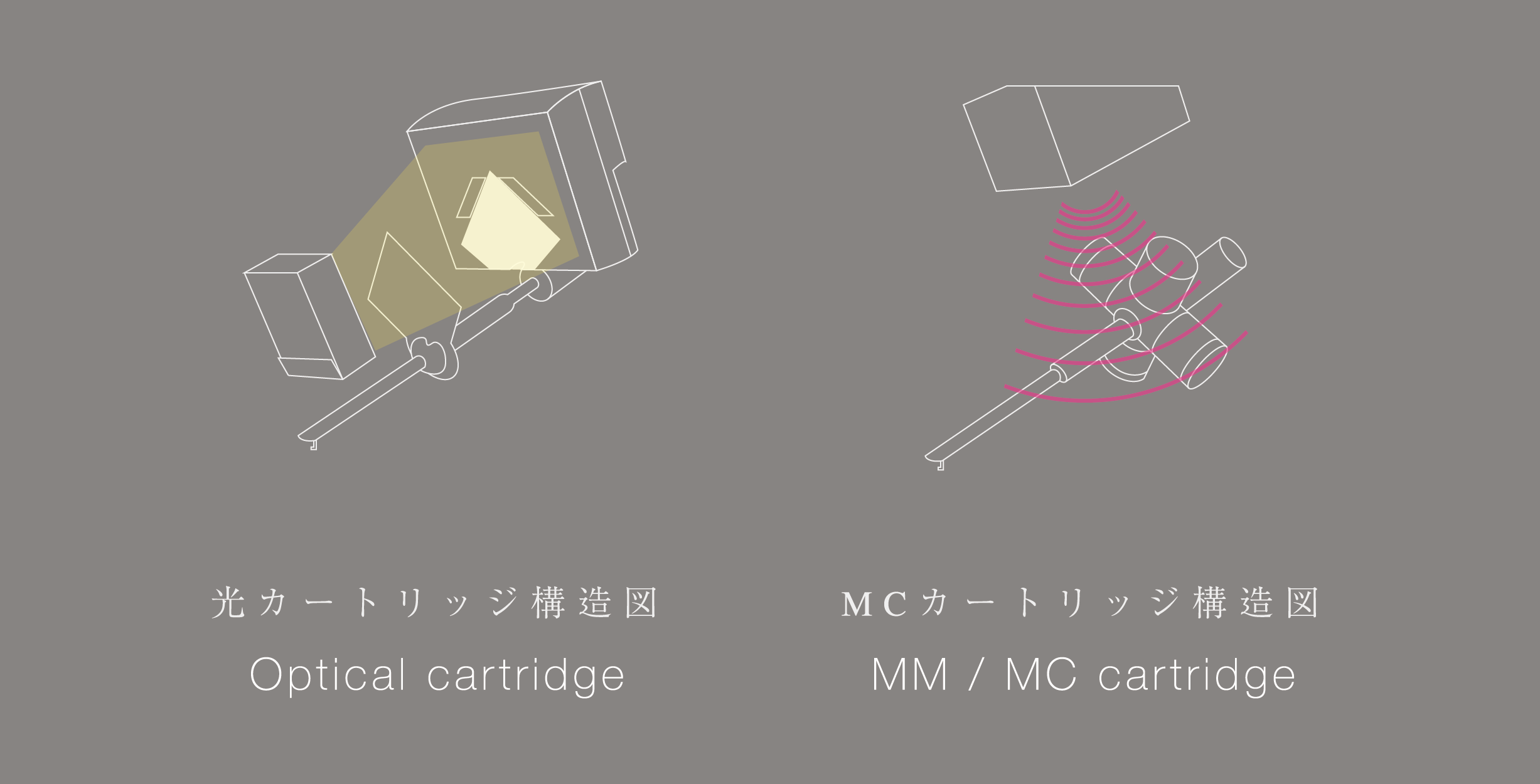
またMM/MCカートリッジは音楽信号を検出する為にマグネットまたはコアとコイルを動かさなければなりませんが、
光カートリッジの場合はわずか100ミクロンの厚みの薄い遮光板を動かすだけで良いため実行質量が極めて軽いというメリットが2つ目の光カートリッジの原理的なメリットになります。
First, We will explain the difference of detection principle between the optical cartridge and MM / MC cartridge.
Both the MM / MC cartridge and the optical cartridge read the record groove through the needle, but the usual MM / MC cartridge detects the music signal by vibrating the magnet (or coil) in the magnetic field.
On the other hand, optical cartridges detect music signals by capturing shadow changes (brightness changes) using LEDs and PD (photo cells).
Because MM / MC cartridges generate electricity by cutting off the magnetic field, magnetic resistance always occurs when the magnet (or coil) moves.

However, the optical cartridge detects only the change in brightness (shadow movement), so no magnetic resistance is generated when the vibration system moves.
Since there is no magnetic resistance applied to the vibration system, the tip of the needle can move smoothly.
This is the primary advantage of optical cartridge technology.
To detect music signals, the MM / MC cartridge must move the magnet or the core and the coil. However, in the case of optical cartridges, it is only necessary to move a light shading plate with a thickness of only 100 microns, so the moving mass is very low.
This is an additional advantage of optical cartridge technology
| MM/MCカートリッジ | 光カートリッジ | |
| 磁気抵抗 | あり | なし |
| 実効質量 | 重い | 軽い |
| MM/MC cartridge | Optical cartridge | |
| Magnetic Resistance | Yes | No |
| Moving Mass | Heavy | Light |
光カートリッジの検出原理とは?
What is the detection principle of the optical cartridge?
ここで光カートリッジの検出原理をもう少し細かく説明致します。
光カートリッジは赤外線LEDと遮光板と2つのPD(太陽電池)を使い針の動きを検出します。
動作原理は至って簡単でLEDの前で遮光板が振動し、その後ろにあるPD(太陽電池)が明るさの変化を検出します。
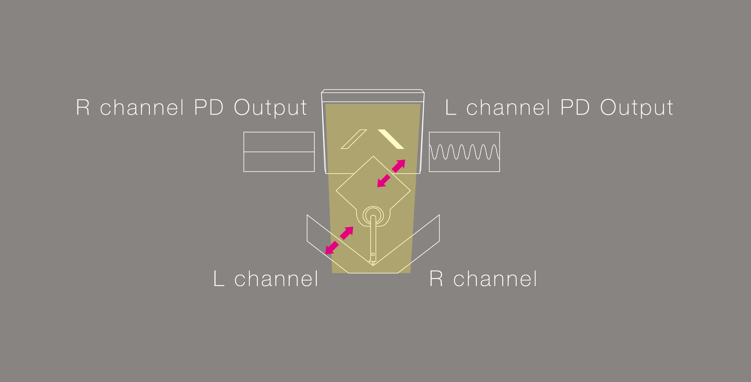
ここで明るさの変化からどのようにL,Rチャンネルの信号を独立して検出するかを説明致します。
上の図はLEDがある位置から遮光板と太陽電池を見た図となりますが、レコードの溝が振動(斜め45度方向)すると振動は針先からカンチレバーに伝わり遮光板も共に振動します。
遮光板が正面のLEDの光を遮るような形で振動することで、PD(太陽電池)へ入る明るさは、明るい→暗い→明るい→暗いと連続的に変化します。
そしてPD(太陽電池)はその明るさの変化=レコード盤の溝の動きを電圧変化としてそのまま出力します。
その際に逆のPD(太陽電池)側は遮光板の動きが平行移動となることで太陽電池の明るさは変化しない為、一つの遮光板で左右2チャンネルのオーディオ信号を検出をすることが可能になっております。
この基本的な検出原理は40年前の光電式カートリッジと全く同じです。
ここでご理解頂きたいのはPD(太陽電池)の出力は遮光板の動き=レコード盤の動きそのものをそのまま電圧変化として出力しており、
一切デジタル化などといったことはされていない完全なアナログサウンドであるということです。
We will explain the detection principle of the optical cartridge in more detail.
The optical cartridge detects movement of the needle using infrared LED, light shielding plate and two PD (photo cells).
The operating principle is simple, the shading plate vibrates in front of the LED, and the PD (photo cells) behind it detects the change in brightness.
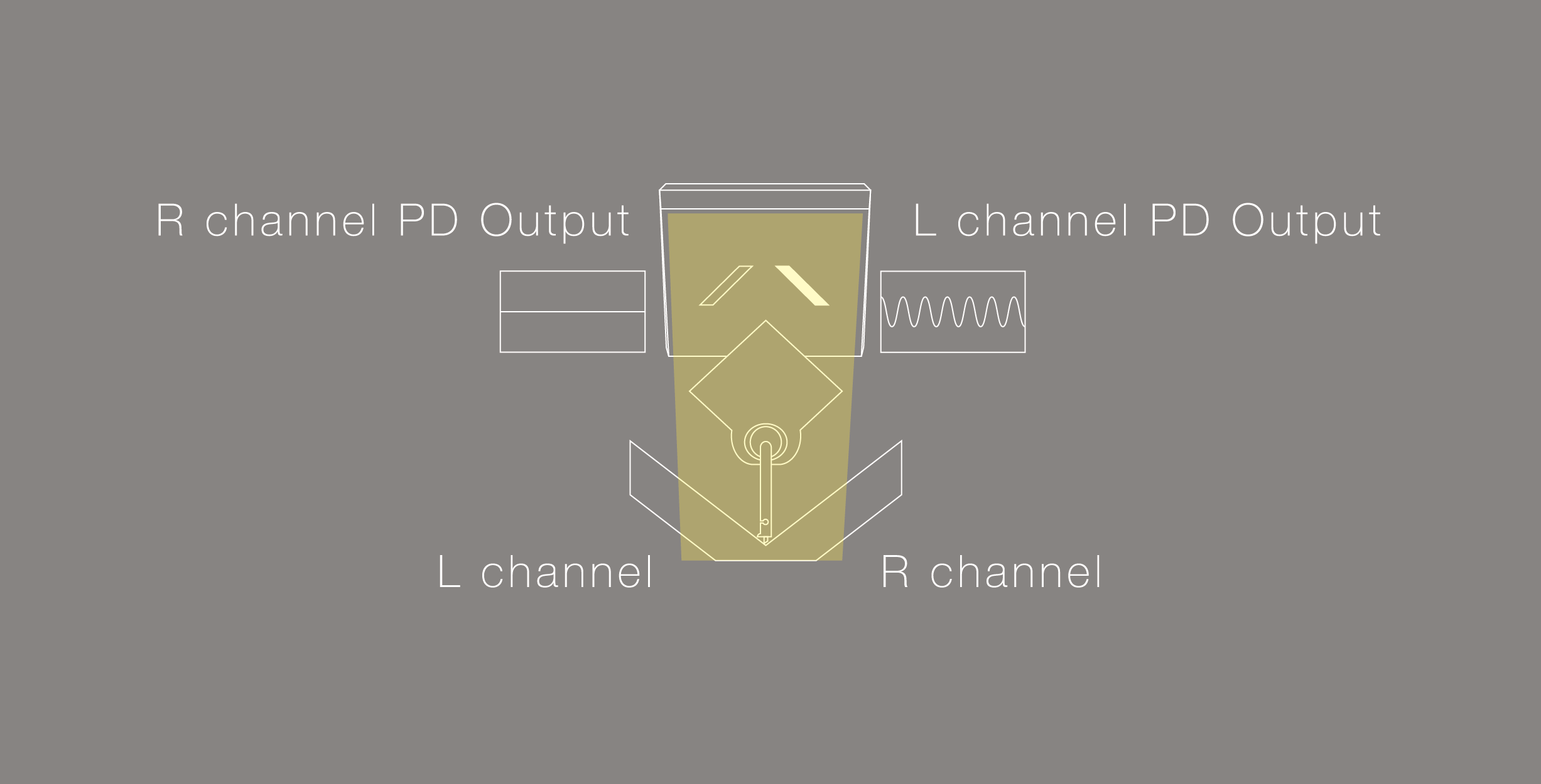
We will explain how to independently detect L and R channel signals from one shading plate.
The above diagram is a view of the light shielding plate and the photo cells from the position where the LED is located.
When the groove of the record vibrates (oblique 45 degrees), the vibration is transmitted from the tip of the needle to the cantilever, and the shading plate also vibrates together.
Since the shading plate vibrates in such a way as to block the light of the front LED, the brightness entering PD (photo cells) changes continuously from bright → dark → bright → dark.
As the photo cells detect changes in brightness created by record groove movement, the output voltage changes accordingly
The movement of the shielding plate will be read as 2 separate stereo channels, by 2 independent photo detectors.
The angular movement of the shielding plate ensures that each photo detector can only pick up information from its corresponding channel. Information from the parallel movement of the opposite channel will not be read, ensuring accurate channel balance and channel separation.
※Since the brightness of the photo cell does not change because the motion of the light shielding plate becomes a parallel movement on the side of the reverse PD (photo cells) side, it is possible to detect audio signals of the left and right channels with one light shielding plate.
This basic detection principle is exactly the same as the photoelectric cartridge 40 years ago.
The important point here is that the output of the PD (photo cell) is the Pure analog sound because the movement of the shading plate = the motion of the record board is output as a voltage change. It is NOT Digital Sound.
| MM/MCカートリッジ | 光カートリッジ | |
| 出力 | アナログ | アナログ |
| MM/MC cartridge | Optical cartridge | |
| Output | Analog | Analog |

専用イコライザーが必要な理由
The reason why you need a dedicated equalizer
光カートリッジではMM/MC用のフォノイコライザーを使用することは出来ず、DS Audioの光カートリッジ専用のフォノイコライザーを使用して頂かなければなりません。
その理由は以下の2つの理由です。
①カートリッジにLEDを使用している関係上カートリッジに対して電源供給が必要であるが、その電源供給をイコライザーから行なっているため
光カートリッジのLEDへの電源供給はトーンアームのグランド(青色と緑色のライン)を使って電源供給しております。
その為光カートリッジをご使用頂くにはトーンアームの4本のケーブルがきちんと独立していることが必須となります。
(現在流通しているトーンアームであれば、ほぼ全て問題なくご使用頂けます。)
②RIAA補正に必要な電気回路がMM/MCカートリッジのものと全く異なるため
MM/MCカートリッジの出力は速度に比例する速度比例型の為速度の上がるごと(=高い周波数になると)に出力が増加します。しかし光カートリッジ(昔のクリスタル型やコンデンサ型も同様)はレコードの溝の動きをそのまま出力する振幅比例型出力であるため低い周波数から高い周波数までフラットに出力します。
このように振幅比例型に分類される光カートリッジは、速度比例型であるMM/MCカートリッジとは出力形態が異なるため仮に同じレコードを読み取ったとしても全く異なる出力が得られます。
その為当然RIAA補正に必要な電気回路も振幅比例型カートリッジ用のRIAA補正回路と速度比例型カートリッジ用のRIAA補正回路は異なったものとなってきます。
これが光カートリッジを使用する際に専用のフォノイコライザーが必要となってしまう2つ目の理由になります。
なお振幅比例型の光カートリッジは低い周波数から高い周波数まで溝の動きをそのままフラットに出力できる為、光カートリッジのRIAA補正回路は速度比例型のRIAAイコライザー回路に比べて圧倒的にシンプルな回路となります。
フォノイコライザーカーブの補正回路がMM/MC用のフォノイコライザーに比べて圧倒的にシンプルな回路に出来ることこれも光カートリッジの大きなメリットの一つとなっております。
With an optical cartridge, you can not use a phono equalizer for MM / MC, you must use a phono equalizer dedicated to the DS Audio optical cartridge.
There are two reasons for this
① Voltage is required in order to power the internal LED inside the cartridge, and this voltage is supplied by the equalizer
Power is supplied to the LEDs of the optical cartridge using the tone arm ground (blue and green lines).
For that reason, in order to use the optical cartridge, it is essential that the four cables of the tone arm are properly independent.
(There is no problem with most arms that are currently on the market.)
② The standard RIAA equalization curve required for MM/MC is completely different from equalization required for optical cartridges.
Because the output of an MM / MC cartridge is proportional to its speed, the output increases as the speed rises (= higher frequency). However, the optical cartridge has an amplitude proportional output that outputs flat from the low frequency to the high frequency (same as the old crystal type and capacitor type).
Since the optical cartridge is classified as amplitude proportional and is not affected by changes in speed, even on the same record, it has totally different output properties. Much less EQ correction is required for the amplitude proportional output compared to traditional MM / MC. Because of this, the RIAA correction circuit of the optical cartridge requires much less manipulation of the signal compared to a speed proportional type MM / MC cartridge.
The RIAA correction circuit of the optical cartridge becomes an overwhelmingly simple circuit.
This is yet another advantage of optical cartridge technology
The amplitude proportional type optical cartridge can output the movement of the groove flat from the low frequency to the high frequency, so the RIAA correction circuit of the optical cartridge becomes an overwhelmingly simple circuit compared to the RIAA correction circuit of the speed proportional type.
The RIAA correction circuit of the optical cartridge becomes an overwhelmingly simple circuit.
This is also big merit of the optical cartridge.

40年前に発売されていた光電式カートリッジとDS Audio光カートリッジの違いについて
Improvements over older optical designs
ご存知の方も多いかとは思いますが、今から40年以上前にも東芝、シャープ、トリオ、ケンウッドなどから光電式カートリッジは製品化されていました。
一度製品化された光電式カートリッジが姿を消してしまったのは、発売された1970年代は大手会社の開発資源がアナログからCDへ移行したことが一番大きな理由かとは思いますが、
過去の光電式カートリッジにはどうしても克服できなかった一つの課題がありました。
それは「熱」の問題です。
今から40年前には現在のようにLEDなどはなく、光電式カートリッジに使用できる光源はランプしかありませんでした。
このランプを光らせると大量の熱を放出し、その熱がカートリッジのダンパーゴムを暖めてしまうことで時間が経つにつれてダンパーゴムがどんどん柔らかくなってしまいコンプライアンスが変化してしまう(音色が変化していってしまう)という問題がありました。この問題を克服する為に各社様々な工夫をしていたようですが抜本的な解決策は見つからないまま光電式カートリッジは姿を消してしまいました。しかしこの頃から磁気から解放された光電式カートリッジのクリーンで鮮度の高い音質自体は非常に高く評価されており、その後40年以上に渡り「伝説の銘機」として語り継がれて来ました。
ここで何故DS Audioが40年の時を経て光電式カートリッジを復活させられたかというと、一番大きな理由は40年間の間に発光素子、受光素子共にデバイスが大きく進化したことです。
現在は40年前と違い非常に小型で高出力なLEDを使用出来る為昔のように熱の問題が発生しません。
(家庭の電気でも蛍光灯の頃の電球は熱かったかと思いますが、LED電球にすれば熱くならないのと同じイメージです)
そして光源の波長にしっかり感度特性の合った高感度なフォトダイオード(光源の波長でもっとも感度が良く動作する受光素子)を使用出来る為、
非常に高い出力(約70mV)を取り出すことが可能となっております。
光カートリッジの出力は約70mVとMM/MCカートリッジと比較すると約10倍〜100倍にもなる高出力を得られる為、
トーンアーム内を微弱電流で通す必要がない点もMM/MCカートリッジにない大きな魅力の一つとなっております。
As you probably know, some photoelectric cartridges have been commercialized from Toshiba, Sharp, Trio, Kenwood etc over 40 years ago.
The reason why the optical cartridge once commercialized disappeared is that in the 1970s, it is the biggest factor that the development resources of major companies have shifted from analog to CD.
In addition to that, there was one problem that could not be overcome in the past optical cartridges by any means.
That is a problem of “Heat”.
Forty years ago, LED technology was not well developed, and the only light source available for an optical cartridge was a standard style bulb. These bulbs generated a large amount of heat, which warmed the damper rubber of the cartridge, softening it over time and changing the compliance characteristics. Each company took various measures to overcome this issue, but optical cartridges disappeared from the market before a fundamental solution could be found. Even with this drawback, the sheer quality of the sound of optical cartridges gave the technology a legendary status for over 40 years.
40年前の光電式カートリッジ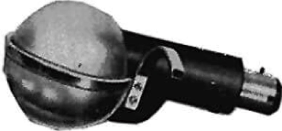 |
DS Audioの光カートリッジ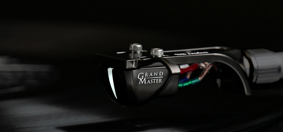 |
|
| 光源 | ランプ | 赤外線LED |
| 受光素子 | フォトトランジスタ | 感度特性の適切に合ったフォトダイオード |
Optical cartridge 40 years ago |
DS Audio Optical cartridge |
|
| Light Source | Lamp | LED |
| Light Receiving Element | Phototransistor | Photodiodes with matching sensitivity characteristics |
